There are many cables out there, but since the G540 came with the connectors I may as well use them. So my plan is to just get a roll of 22awg or bigger wire to make all the connectors. I just need to figure out how many wires are actually needed for each motor. Assuming I get 4 wire motors, but honestly I don't know since I'm not there yet.
So far it looks like the gecko uses motors with only four wires, so this narrows down your search for motors a tiny bit. Since I'm doing this system build from scratch, you can get the wire after you get the motors. It may be easier to choose the wire once you know what your motors have. I think 22awg may be a standard for nema 23, but I'm just guessing here. So I'll wait until I have the steppers in hand before I go looking for wire to make my motor connections. You can also just buy smaller lengths instead of a roll like I wrote above. It will be more affordable and you won't have left over wire. I think I saw 12 and 25 ft pieces at one store, so look around to find what works for you.
This past week I bought the resistors I will need to use with my motors. Depending on the motor specifications, you may or may not need them. This only applies here if you're using the G540. According to the manual you take the current, multiply that by 1000. In my case the each motor is 3amps x 1000= a 3k ohm resistor. So I'll be adding the pictures for the wiring here.
https://picasaweb.google.com/jaimenow/CNCWiring?authuser=0&authkey=Gv1sRgCLKhjeum2-PvaA&feat=directlink
I have ordered the XLR-4 male and female connectors on this page. I want to keep them in line with the wires and will try to keep this as neat as possible. They seem perfect so I hope these will work.
http://www.futurlec.com/XLR-4Pin.shtml
I finally received the xlr connectors, unfortunately they got my order wrong. They sent me all males and no females! Not cool. I already added the pictures on the above link. I found you can get these connectors in black as well which I like better since you have less parts to take apart.
Aug 1, 2012
Here's the first type I was considering, but these can be used in a case and since I just want the inline type above. I did order two sets of these to compare and well, maybe use on the lathe if I ever cnc it.
http://www.futurlec.com/XLR-MIC.shtml
Today I received my e-stop switch in the mail. It's all mainly plastic and it does feel pretty cheap, but hey, it's a switch. It is not that small so I'm a bit bummed out by that, but again, it is what it is. The pictures are on the first link above.
July 20, 2012
January 14, 2012
I finally decided to get these motors wired. For the motor wires, I just went ahead and used 3M electrical tape to keep them together and protected. I can use wire loom later if need be.

I decided to just add these quick connectors. These were the second ones I received. They are a bit heavy but these are going to be sitting on a table so it's not bad. I decided to just solder straight to the motor wires without anything else on them to make them easy to swap if need be.

Here's where I need to solder the wires to. Now how do I do that in here...hmmm...

This is the other side. I chose to use the pin side of the plug on the motor wires. When unplugged I don't have to worry about having power pins/wires exposed.

Although they looked pretty tough to figure out, all I needed to do was to push the internal piece out the back. It just slides out so it's not hard to get them out which was really nice. My color wiring on the motors were:
1. Red
2. Yellow
3. Green
4. Blue
The center pieces are numbered inside and outside. I ended up using 16 gauge wire for the controller plug and longer plug to the motors. I used this thicker wire because it was free, but even though I was able to solder it, it's a bit too thick, so go with 18 or 20 gauge wire, that should be perfect and easier to solder to these small tabs.
The colors are almost irrelevant since all you need to know is which pair makes a phase on the motor. Once you have one pair, the other pair is your other phase. Assuming you only have four wires like my motors. Although it helps if your motor specification sheet tells you the colors and phase so you can wire them correctly from the start. The colors on my 16 gauge wire are:
1. Red
2. White
3. Green
4. Black

I finally got my first one all soldered! Well not so fast, I did do a nice job with soldering, but I forgot to put the bottom cap and wire holder in before doing the soldering. So I had to de-solder the whole thing put those items in, then solder all my motors again. Hey, somethings you get a brain fart. LOL


The inner piece tab aligns with the opening on metal housing, the plastic holder has a tab that aligns with the bottom inner groove. Everything just slides in so this is the easy part.


I found the easiest way to solder the wires so you get the correct match was to plug in both inner pieces and do the soldering. Just make sure you put your boots and other pieces in before making the solder.


Here are my motor side connections finally done. I The white wire is just some stranded speaker wire I had laying around and it's pretty heavy duty. I just measured across my arms to get the length I wanted as I didn't want them to be too long.

The next step was to get the resistors on my plugs and get all those tiny pins tinned with solder.

Here's the first one done. It's not hard, but you will surely get burned a bit. Use the correct one for your application. I was scratching my head as to where I was supposed to put them, but if you look at the controller, the print on them shows you were it goes.


All done! Well almost. The hard part is going to be soldering the other wire end to these pins. Unfortunately my motors spec sheet doesn't say which side is Phase A and which is Phase B or which is negative or positive for the wires. I do know the colors, but the controller only has A and B labeled. I sent an email to the store I bought them from so I can hopefully get these soldered correctly from the start. I know it's a 50/50 chance, but I really don't want to redo this part again. This is why it's important to have that on the specification sheet of your motors as I'm finding out. I don't have a program to test them with so I'm just going by the actual power test once I get them soldered for now.

I have been playing with the motors to find out a bit more how they work. Here's a video of what I found out. I have also been reading a bit more on them as it's been a while since I looked into them.
Here's how I ended up soldering this one motor.

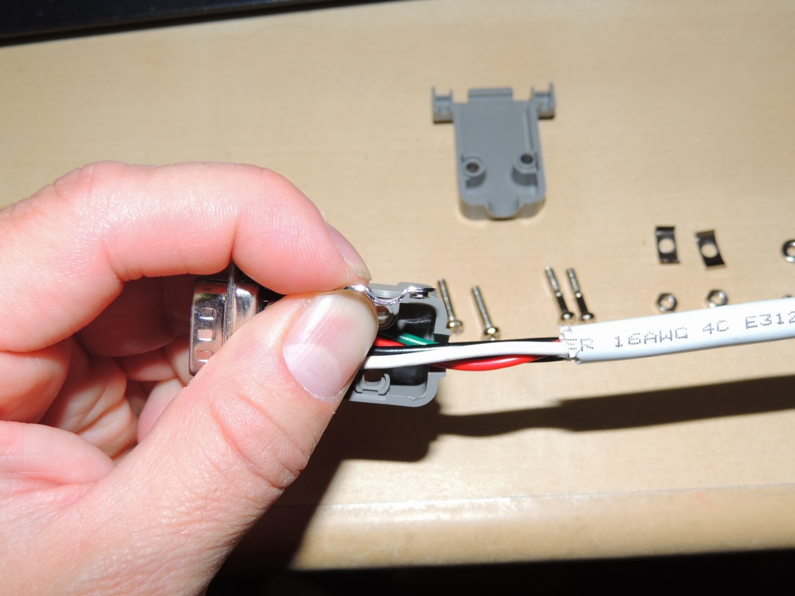
I also had to figure out how to get the cover installed on these plugs, but I figured it out and since I couldn't find any instructions anywhere, I took pictures to help others get these installed.
This are all the parts included in each bag.

Here I placed one of the covers under it. It fit perfectly.

These pieces have threads on one side. I thought they went over the plastic holes above, but they just would not aligned correctly.
I then figured these to pieces can only be installed like this on the wires. One screw from each side.

I did checked the distance where to install it with the plastic piece on.


Here I tested the top cover and the side screws. The side screws are the ones with thread on the bottom half only.

So here's where these pieces come in. They actually keep the wires from getting pulled back. Well this is the only place they actually fit without a problem, so I'm going with this. Also, make sure to install those screw side tabs that cover the plastic sides after the two covers are installed.

You should now have them like this. Those side screws need to be put in while the halves are slightly open because that's what holds them in place and keeps them from coming out. So don't force them with the covers closed. So now they should work just like the computer monitor vga plugs.


Now it's time to add the cover screws and nuts. You should now end up with a complete connector shown below. After I figured it out, I took them apart again and used a bit of blue thread lock to make sure the screws didn't come lose inside and outsided after I snug them down.

I won't do the other plugs just yet until I have a chanced to get a computer set up and I can test the motors. I just wanted to cover all the steps since I just did all this today.

So far the only problem I see at the moment is the cheap ebay emergency switch. When pushed it will not lock, so this means I have to keep it pressed in order to be able to move the motor. So I will probably need to replace it with a locking emergency switch eventually. Well that's my guess, but until I get to actually use the system I can't say for sure.


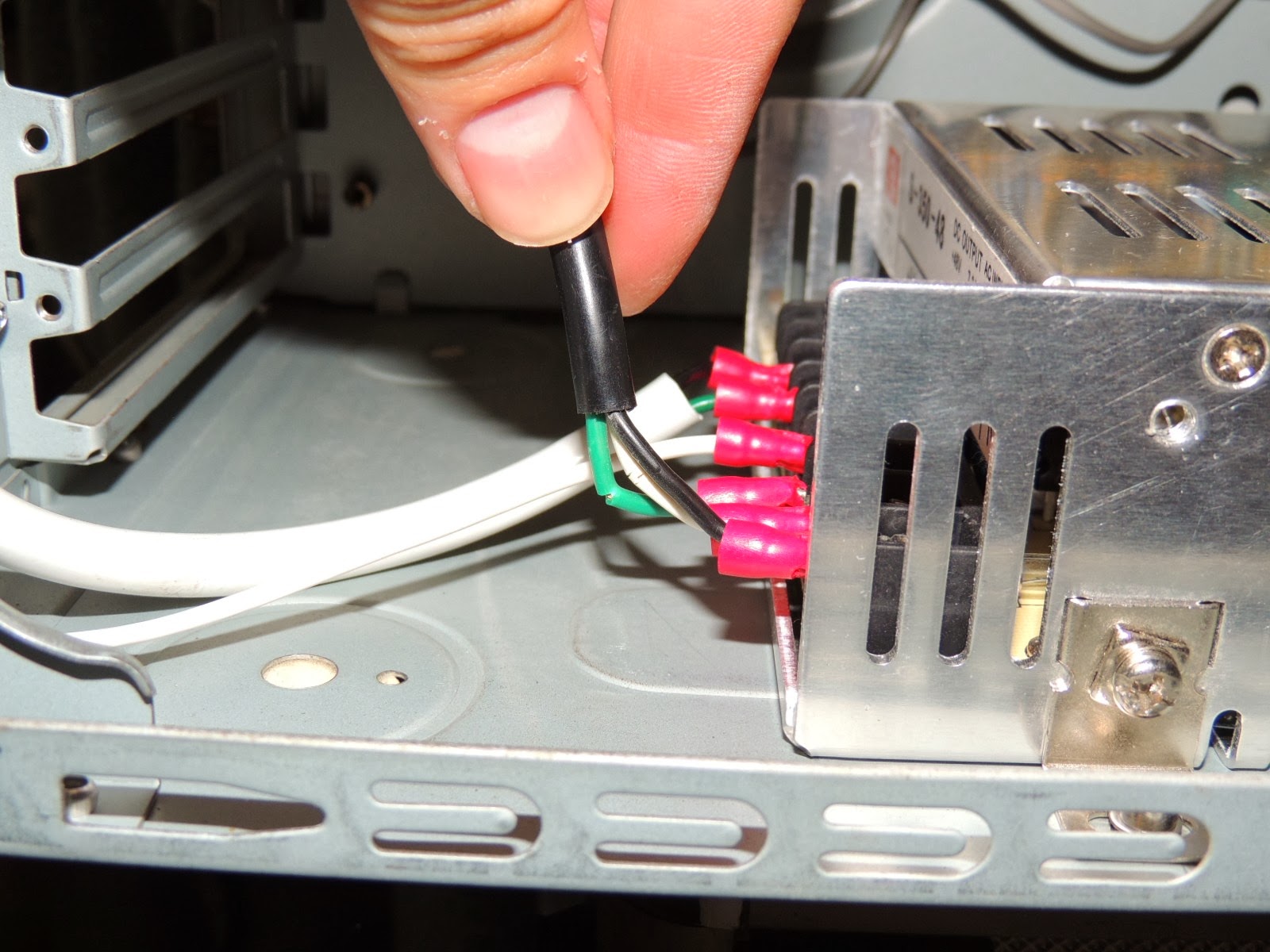
I drilled and tapped four 3mm holes on the bottom to mount the gecko power supply.


1 comment:
Today I decided to just finish the wiring. I got tired of looking at these cables. I thought about just ordering some 20 gauge wire, but they didn't have all the colors to match the motors, so I decided to make the 16 gauge work. It was a pain but I got everything soldered. So if you're doing the same just use 20 gauge wire. It's almost or the same as the motors anyway and I think you'll be fine. I just had this other wire so I might as well use it, but it's too thick and makes it very hard to solder to those tiny pins on the db9 and they are too close if any of your solder comes undone. There's barely enough room to put heat shrink on there too, so this is why I recommend using the smaller gauge. Your soldering will go much faster and easier. So I'll test the wires together. I also decide do make the fourth cable since I already have all the parts, but only three motors. I figure if I get a bad cable I can just use that one too. Either way i just wanted to get this part done. The cables and connectors are pretty heavy, so if you can find smaller ones try those. I think most of the wiring is done. There's still more to do, but I'm getting there.
Post a Comment