I like doing different things so I hope some of this is helpful, or at least an interesting read for you.
Installing new 3D Printer Power Supply on Craftbot
July 9, 2016
My printer finally started giving me some problems while printing and even though I already changed the heater and thermistor, it was stopping right before the first layer of my print was finished. I have also changed the hot end ptfe holder to the aluminum due to the other problem I had with the filament melting through the threads and loosening the hot end. So I got this 12v 30 amp power supply through amazon and just finished installing it. I have the original craftbot printer from the indigogo which had the old computer style power supply. The new cb + power supply has been updated and it's now 24v instead of 12v like the original. I had no problems printing what I needed with 12v, so this is why I decided to just get a 12v power supply. I also have a few 12 v spare heaters so I might as well keep using those. By the way, craftuniquie does not have a 12v replacement power supply, just a 24v. So you will need to upgrade the heater if you go that route. I can't remember if there is anything else. So make sure to check that before starting/buying anything.
Here's how the package came from amazon. My friend has prime so I was able to get the two day shipping since he ordered it for me.
Here's the only sticker on the box.
And here's your typical 12v 30 amp power supply.
This one has the nice orange plastic cover over the terminals.
Here are the specifications.
The end view.
The bottom.
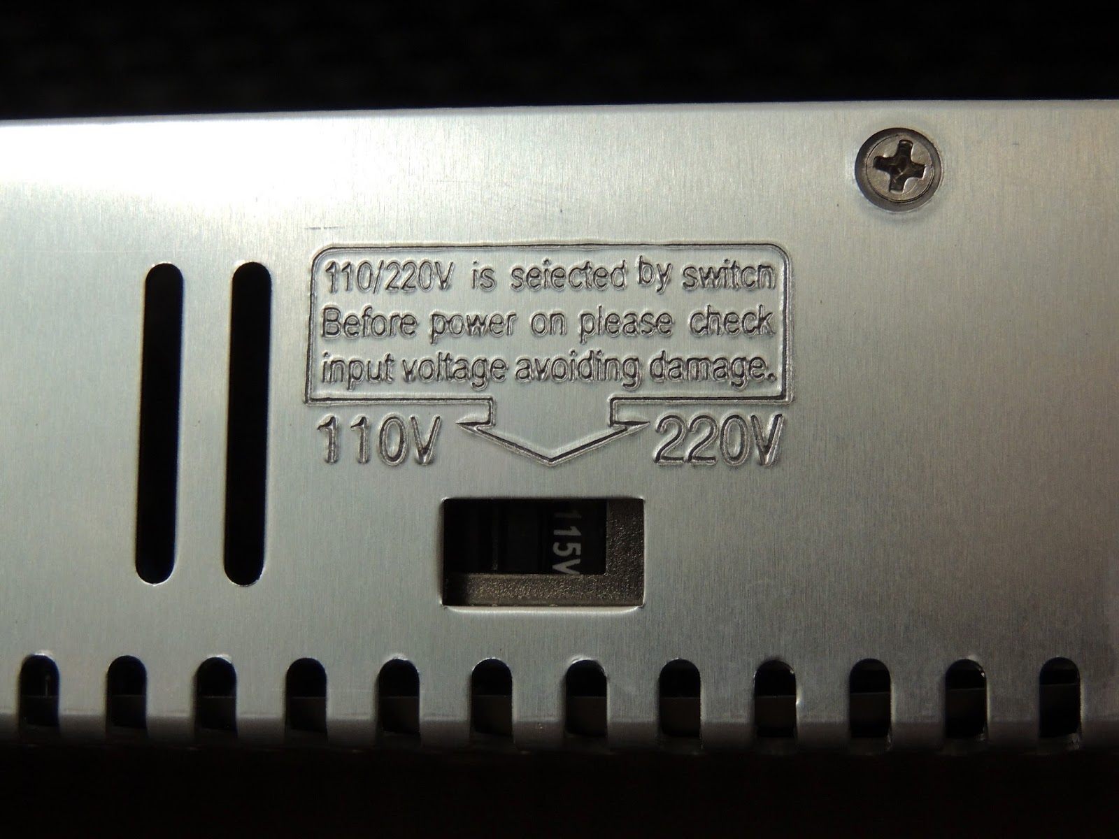
The nicely engraved specifications.
Although the specs say 220v, the actual switch says 230v. Mine came with the switch at 230v so I had to move it. Make sure that you check yours.
The only other part that you will need if you go this route is a computer power extension cable. I decided to go this route to keep things simple and leave the original switch of the cb alone. So no soldering needed here.
Here's the back of the box.
And the two ends. I used the end on the right, since the original is the opposite that goes into the power supply.
Here's what I mean and what this looks like. Yes, this allows me to leave the original switch wiring alone.
The plug fits well and it's not lose which is nice.
The next task was to cut these studs out. I tried using both nuts hoping I could just unscrew them, but I had no luck so I had to cut them down.
I was testing the fit here. The studs got in the way.
In the end, this is what I used to cut them down. I don't have the good dremel here so this is all I could use which made this the longest and hardest part for me. I broke a couple of the disk and only managed to get through half the studs, so I just used pliers to finished them off. I then used one of the other sanding stone bits to take them down as much as I could without scratching the back too much.
Here's what this looked like. I think the disc dust make this more messy than anything, so if you have some large cutters, you could probably do that and save yourself the cleaning part.
Once I finally got it all done.
Testing fit. This wasn't going to work at the bottom since the end is too close to the board and the other side sits on top of the switch getting in the way.
This seemed too tall and moving it down, well, that hides the terminals which I need access to.
So I put three large pieces of this special scotch double sided tape and mounted it. These is a stronger outside tape so it shouldn't come off too easily over time like your cheap white double sided tape. I have been using this instead and it works great. You can get this at your local home depot store if you live in the united states. I'm sure you can find something similar in other countries.
I finally got this mounted and since I had already checked the wires it was no biggie. If you haven't found which wire is which, I suggest doing that before you mount it or it will be very hard to get to the wires, if you can even get to them with the probes. I then cut the power cord to the length I need, but only after mounting the power supply. It just makes it easier I think. Just make sure you place it a bit higher than I have it here in order to leave enough room to take out the wires below if you ever need too. Mine was a bit tight so I thought I mention it. A few mm higher would have been perfect.
This cable shield cutter came in very handy, I did have to re-adjust it to not cut into the wires. Once I did that, it was all good and made my life easier getting these cable ready.
Once I measured and cut the length I needed for the plug side, I then cut another piece from the leftover cable to make the extension that connects to the board from the power supply. The board only has two wires, a positive and a negative. I just strip the shielding enough to allow me to separate the wires and then I just cut the white wire from each end since you have three wires there. I used the black for the positive like the original and the green for the negative/ground which is what the psu uses too.
NOTE: Make sure to plug and test the power supply before connecting the board just to make sure you got your wires on correctly. This way if the power supply doesn't work or fries on you, you don't do that to your board. Once I verified that the power supply turned on correctly, I took my multi meter and checked the voltage to make sure it was 12 v exactly. You can change that a bit with the pot next to the LED, but this one came spot on so I didn't need to do anything.
Here, I powered it up for the first time before connecting the board side. All was good. You can use some connectors on the wires, but the ones I have are not that great so I just put the bare wires under each screw here. Just make sure they are not lose. The automotive connectors are better.
Green is ground
White is neutral
Black is Load or Hot
Here's what this plug looks like. So you only have three wires to connect from here.
And two wires on here. I put my original green connector on one end and stripped the other for the power supply side. You will need to strip the black shielding a bit more on this side since the connections on the psu are a bit more spread out.
All done.
A side view to give you a better look. I leave the rear door off since the original cover doesn't have any holes for the heat to get out and now I got a fan on it too so this should work just fine. I may make some kind of mount to hold the original fan for the board as a test later. This also makes changing the parts quicker since I don't have to take the cover off. Plus it helps to keep things cool on the back anyway.
Here's what both set of wires look like. All you will need to set up are 5 wires! So just take your time and you'll be all set. Youtube has plenty of power supply videos if you need any more help on that so I won't be making any.
A closeup of the terminals.
One last thing, here's a tip for your power cord. Mine seems to fit a bit lose on the back of the switch so I put one layer of electrical tape around the power cord end and and now fits well. Now I just have to make a test print to make sure this takes care of the problem I was having while trying to print anything. I will do this with the current firmware to make sure I also test that before upgrading it since I know they just came out with a new update.
This is the power supply I bought from amazon.
https://www.amazon.com/Elegoo-Universal-Regulated-Switching-Computer/dp/B01GCNZCUG/ref=sr_1_7?ie=UTF8&qid=1467849621&sr=8-7&keywords=12V%2030A%20%20Switching%20Power%20Supply
And here's the video of the power supply turned on.
Update: I decided to make a new part to test out with the new power supply. Unfortunately I am still having the same problem. The temp goes up to 211 and stays there most of the time. It eventually crept up to 212, then once the second layer started the temperature started coming back down again. And this is when the clicking started, again. So I have now changed the heater, thermistor and power supply and still have the same problem. I can't get this hot end to go higher than 212 c. The new file is saved to have a temp of 215 c which is the default for PLA on the firmware 1.1.7864-2015-11-27.
Predator version 1.1.8263-2016-01-09/2. So at this point I have no idea what's going on since I have also checked the parts and they are within specifications.
One other thing I forgot to mention is that you will now hear the fan on the back. It's temperature controlled, but once the bed and hot end heated up, it started going. It blows air out to the back. Other than that, it seems to work just like the original. This one is supposed to have up to 30 amps compared to the original which is 12.5 amps. Of course these numbers can be just an estimate or over rated on these things. I don't have any special equipment or knowledge to test them, but I can make some basic multi meter checks to at least make sure it is 12v.
Update: November 27, 2016
I finally found the problem with the temps. It was an aluminum heatsink that was not letting the extruder reach the correct temps. I changed that to my own ptfe version and all is well again. My printer is back up which is always nice. So having the proper heatsink makes a difference. If it takes the heat away from the block that will surely cause problems/headaches.


1 comment:
Many thanks! It helped a lot!
Post a Comment