March 10, 2016
I finally started printing again since I got my new filament gear from craftunique. I have been having a problem with the prints just not being great, specially on the first layer. So I leveled the bed again, using a filler gauge now to make sure that's consistent. I bought a cheap set just for that since the card stock tends to disintegrate over time. Unfortunately no matter how many times I did that and got the extruder working fine, there would be spots where the clicking would start. I thought it was the bed, but then I decided to stare at the tip while the first layer was printing and sure enough I noticed in some areas the tip would lightly move up, then down during the print. In my case getting way to close to the bed causing the clicking of the extruder. I have worked on getting that extruder back up so I know it's working correctly. I also tried several gears and none have worked with this printer. So the gear on this printer is just weird in the sense that I have yet to find a replacement that will work correctly.
I decided to take the printer apart and take the top left and right guides out to check them for straightness. I heard of this problem before, but just didn't give it much thought until now after I noticed this with my Craftbot. Sure enough, both guides are slightly bent. I don't know if it came that way or not, but I took a few pictures and here are a few notes on this. Obviously this is very important to making good prints. You can add this to the troubleshooting section of any printer with smaller diameter guides.
Here's the type of linear bearings the craftbot uses. I took this one out of the front left side. The printer was facing me. The size is your basic LM8UU bearing. No other marking that I can see.
This is the length. It uses two on each side. So you have a total of four for the two top shafts. The extruder shafts may be the same, but I have not taken that apart so I can't say for sure.
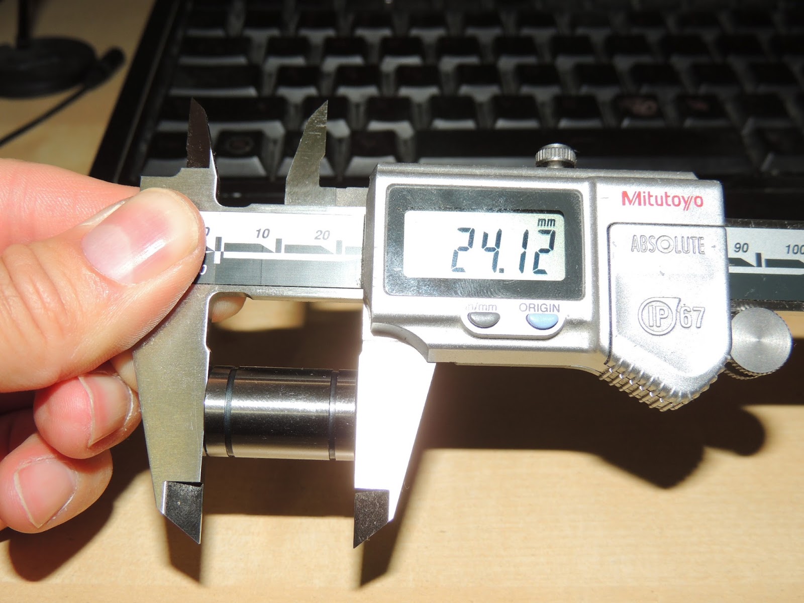
Here's the width.
The inside diameter is a bit harder to take since there's a rubber seal and it's a type of plastic housing. Or what seems like plastic holding the ball bearings. But this should give you an idea.
Here's a look at the inside of the bearing.
Here's the inside of the bearing holder. That small hole inside is where the set screw goes and what holds the bearing in place. You get to it from the bottom. The back one is on the opposite side. You can take these out without taking the belts off, just do one side first, then the other, then lightly set it down in the middle of the machine to keep the weight off the belts as much as possible.
The top. It was very clean in there, so I didn't bother taking out any other bearings. At least from what I could tell. That will happen when I take it all apart for belt changing or whatever is needed then.
Here's the shaft size.
And the total length for the two top shafts. That's about 350 mm. These are the Y axis shaft. The ones the are on the top of the printer and go front to back. I also just measured the lower x shafts on the extruder and they are 330 mm long. I just measure from the end of each block since I have not taken them out but this is what those look like. They all seem to be 8 mm in diameter.


Now here's where I got a bit more curious. Just roll these on a table and you can usually tell if it's bent without anything else. Once I did this, I slowly turned the shaft so that the sagging or bent part would face up. Look at it straight ahead from the side in order to see that. I then marked the shaft. The reason I did this was to make sure I re-installed it on the opposite side. On the second shaft I marked it towards the middle before taking it off. I then did the same thing of marking the opposite side once I rolled it on the table and sure enough, it was just opposite of my first mark. Just make the mark towards the end, but not at the end since that goes into that white plastic piece and you won't see the mark. This is why you see two marks in the picture above. Live and learn. So this is basically what I did since I don't have any new shafts and because of the sag or bend, whatever you want to call it, the extruder was getting lowered in some areas causing the clicking. With that said, this is still not what you want, you want straight shafts, but since I don't have any, I decided to give this a try for now. I still heard like two slight clicks this time as I am printing, but it seems to have actually helped in that respect. I thought it would be doing the opposite and I notice it missed one area but it was doing it before too. I still hear a few clicks here and there, but everything seems to be working still so I'll say that's probably due to the shafts since they are still bent. I did not check the lower shafts though. That means you really have to take it all apart which I really didn't want to do since I don't have any spare parts and you need to pull the whole gantry up. Not a big deal, but there's just no point in doing that now. I wanted to test this with the two changes I did.


As I was putting it back together, this fell out. It goes on one of the rear holes. so now I don't have thread back there.
In conclusion, this seems to be a problem with other printers too. I think the way to fix this is getting some better shafts or making the printers with larger diameter shafts. I noticed other printers had sliders that sat on a ledge of a printer side which now makes sense why they made them that way. This would increase the weight a bit, but at least you won't have this bent/sagging problem. I've only had my printer for exactly a year so this is no fun finding out.


1 comment:
Post a Comment